interesting.
ive had this schematic floating around, and recent events have had me returning, and finally experimenting.
i tore down a magneto, and found the wire soldered to the laminations isnt a centre tap but the start of the entire coil. a major flaw, i feel...
but it returned me to the cdi scheme of things in the search of more get up and go!
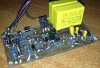
five minutes, and the things point to point wired. about the size of my thumb. pretty neat
so, i tried the 33 ohm and 100 trimmer(200 was all i found) and, when hooked up to a handy 6v c90 coil, worked! that blows my mind, that it works on a standard points type induction coil!
then the resistors burnt and fried. heh heh heh.
up graded to the 18 and 82 version. fried
")
ok, heavier resistors... and besides one really hot resistor, im getting a spark with only 15volts! a multitap transformer is so handy at times. if only i had variable frequency too!
30 volts is nicer
im guessing most of my frying issue now is due to using a 1 amp transformer at only 30volts and 50 hz... IR^2 and all that nonsense about duty cycles? they take a lot of current on one cycle!
the stock cdi doesnt do anything, and i dont have a transformer over 30v handy to push it either.
wondering what would happen if i stuck it on mains via an isolator at 240?
anyways. ive noticed OP hasnt been around for some time... thanks all the same dude.
i shall do a run for real tomorrow!
just, some things i noticed went dead ended...
on the tear down, there appeared to be a zener diode in the circuit?
ive been contemplating this avenue before reading all this, so i picked up on it...
but what i just wrote i deleted as i can see now that it would have no effect on the advance curve at all.
so what the bejeesis is it doing in there? it never was mentioned again
oh well. try my hand at depotting.
plans? oh, i got plans...like a twin spark ignition coil, properly potted for all these multi plug heads ...?
a basic dyno in the near future for mod testing.
and such forth nonsense


 s old.