4 diode AC to DC circuit?

GoldenMotor.com

mew905

New Member
Sep 24, 2012
647
9
0
Moose Jaw
Would this work as an AC to DC circuit? I'm aware the DC current would be ridiculously rippled but that can be fixed with caps I'd imagine. If this is basically the start point for the rectifier already listed on the forums, I apologize, I have trouble reading wiring diagrams.


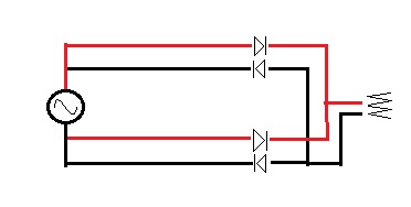
EDIT: took a long hard look at the wiring diagram at the bottom of the first page on the DIY rectifier page, and noticed that what I have here, is a larger version of the bridge rectifier. Neat. while it makes this thread pointless, I have to say I understand it a little bit better now that I've figured out how to build the bridge rectifier outside of the IC (however the IC would obviously be much smaller)
 

Attachments

Last edited:

rohmell

Active Member
Jun 2, 2010
1,531
6
38
New York
I don't know if this helps any, but here's how to remember how to draw a bridge rectifier:

Draw a diamond:


Add diodes, all pointing in the same direction:


The diodes 'point' towards positive, and away from negative, and halfway in-between is where you add AC:
 

dracothered

New Member
Jul 25, 2012
973
1
0
Howell, MI.
From what I understand about the power out from the White wire if that is what you plan on using is it is only right around 6v and not enough current to run the lights. So this is why I did this circuit diagram which should give you the voltage needed to charge a 6v battery and run your lights from that.


Attachments

mew905

New Member
Sep 24, 2012
647
9
0
Moose Jaw
From what I understand about the power out from the White wire if that is what you plan on using is it is only right around 6v and not enough current to run the lights. So this is why I did this circuit diagram which should give you the voltage needed to charge a 6v battery and run your lights from that.

Nono, I plan on grabbing a 12v mini gen and then using my own LED brake/signal lights (not sure what I'm going to do about a headlight, I'm not confident even in 10,000 MCD super bright white LED's for a headlight, I want a parabolic one that can focus it more effectively).
 

BigBlue

Member
Nov 29, 2011
781
0
16
California
Nono, I plan on grabbing a 12v mini gen and then using my own LED brake/signal lights (not sure what I'm going to do about a headlight, I'm not confident even in 10,000 MCD super bright white LED's for a headlight, I want a parabolic one that can focus it more effectively).
12v mini gen? Are you talking about a Wonderful Creations 12v mini gen that produces 12 Volt A/C? So what you are looking at is designing a single phase rectifier?
http://motorbicycling.com/attachment.php?attachmentid=54475&stc=1&d=1355683187


Chris
AKA: BigBlue
 

Attachments

Last edited:

mew905

New Member
Sep 24, 2012
647
9
0
Moose Jaw
yup, a 100uF cap as far as I could see in combination with a 100ohm resistor afterwards produces a relatively stable DC signal, vDroop is only around 0.02v . However I'm having trouble (perhaps I missed it on the ebay page?) finding how much amperage either of these mini gens is capable of producing.

EDIT: checking the site again, it says it produces 12v AC at 1300-1500 RPM (I think thats idle? they say its 15-18mph riding speed though). and "Over 18 volts and up to 1.5 amps at high speeds", or 27 watts (? I'm not sure if AC wattage is calculated the same as DC wattage) but that's essentially 18v @ 110hz (6600RPM) x 1.5a

EDIT2: how would I go about stabilizing the voltage to 12 volts output if the input can be anywhere between 12 and 18v? I'm thinking I'd need a MOSFET, however Wikipedia and a couple other sites show use of a 7812 IC I believe.
 
Last edited:

dracothered

New Member
Jul 25, 2012
973
1
0
Howell, MI.
yup, a 100uF cap as far as I could see in combination with a 100ohm resistor afterwards produces a relatively stable DC signal, vDroop is only around 0.02v . However I'm having trouble (perhaps I missed it on the ebay page?) finding how much amperage either of these mini gens is capable of producing.

EDIT: checking the site again, it says it produces 12v AC at 1300-1500 RPM (I think thats idle? they say its 15-18mph riding speed though). and "Over 18 volts and up to 1.5 amps at high speeds", or 27 watts (? I'm not sure if AC wattage is calculated the same as DC wattage) but that's essentially 18v @ 110hz (6600RPM) x 1.5a

EDIT2: how would I go about stabilizing the voltage to 12 volts output if the input can be anywhere between 12 and 18v? I'm thinking I'd need a MOSFET, however Wikipedia and a couple other sites show use of a 7812 IC I believe.
Remember the LM7812 is only good for 1amp, so you will need a way to regulate your voltage that will handle a higher amperage output. Luckily you can still use a LM7812 with and added transistor to create a high amp regulator.


Attachments

mew905

New Member
Sep 24, 2012
647
9
0
Moose Jaw
I'm slowly learning, I'm trying to figure out how to get constant 12vDC to a load after being converted to DC, I have no idea how to use transistors, op-amps or MOSFETs, but there is a wiring diagram for a voltage regulator that outputs 12v -+0.1v from an AC source, but it has like 4 grounding points, a zener diode (thank you wikipedia for explaining this haha) an OP-amp, and a transistor I believe.

this is what I've been playing with to learn: http://www.falstad.com/circuit/

EDIT: playing with the editor, I came up with this setup (AC current says 25hz because that's 1500RPM). It outputs 12v -+0.05v, however if you look at the picture, when I added the LED, the amperage went from 0A to 25 2.5x10^26 amps, which... I imagine is pretty impossible, even if the input voltage was much, much higher, which leads me to believe that this circuit wont work. Can any one of you electronic guys spot where the circuit is wrong?


Attachments

Last edited: