

That then begs the question, why does the cdi have a ground wire if the circut is completed through the spark plug and engine? The whole system seems more complicated than it really needs to be. I'm going to get my father to take a look at it and see what he comes up with.
Shift kit + expansion chamber
- Thread starter Spaz_Static
- Start date

One thing I'm thinking of doing is to take the ground wire, solder it to the common ground directly (make a bare patch in the middle of it or something), possibly pulling up one of the layers of the mag core so that I can heat it easier, have another part of the ground attached to the engine directly, and let the other end connect to the cdi. ...something like that anyway.
another thought, and to maybe save a few bucks, is to re-roll it, eh? Those little dinky wires are a pain to repair, and if they're not "just right" null spark...
Food for thought: http://www.google.com/cse?cx=partne...#gsc.tab=0&gsc.q=wind your own cdi&gsc.page=1
Food for thought: http://www.google.com/cse?cx=partne...#gsc.tab=0&gsc.q=wind your own cdi&gsc.page=1
I read through a roll your own mag thread and from what I remember, the guy wasn't having much luck.
Wow, you really are an electrical novice.That then begs the question, why does the cdi have a ground wire if the circut is completed through the spark plug and engine?
It takes TWO METAL CONTACTS to complete ANY electrical systems parts.
Spark power is generate from the magneto in the motor through the CDI.
It has 2 contacts, spark voltage and ground.
The spark plug has 2 contacts, the high voltage spark at the top, and it's ground through the motor to the magneto.
In between is the Capacitor Discharge Ignition (CDI) module, the black box with the spark plug wire and TWO thin wires.
Remember, ALL electrical circuits need 2 connections, hence the black and blue wires from CDI, but can have more outputs.
What the CDI does is drastically increase the wimpy voltage for the magneto to a voltage high enough to arc across a spark plug gap and fire up your motor.
They ALL SHARE A COMMON GROUND FROM THE POWER SOURCE, HENCE THE MAGNETO GROUND!
The wimpy blue wire voltage in is boosted to like 1,000V and that goes out through the spark plug wire.
Heck, if your motor is not insulated from the bike frame with tire tubes or frame paint or something, you can attach the CDI black wire anywhere on the bike frame.
Do you know what a Muiltimeter is?
It is a $12 item at most any Radio Shack or hardware store, and it can measure Multiple types of electrical circuity, hence the name Multi-Meter.
Get one.
Set it to Ohms and use it's two leads to check if you have ground from the Magneto ground lug at the top to the head (for the spark plug) and the black CDI wire as well.
Opening up the magneto, tapping new grounds? Jezz kid, this isn't rocket science and about as easy as it gets.
My advice is just get the cheap tool and learn how to use it, you will find it will be a tool you use for way more things for years to come than your bike like for example seeing if there is power in a wall socket in the AC mode, or if a battery has any voltage in DC mode.
Ya falla? (I couldn't resist that line from the movie The Sting hehehe)
Hence the actual electrical lesson in my 'rude' post.
Spaz was talking about re-wiring the frigg'n magneto for crying out loud, sarcasm does have a place when you feel a person just isn't staring in the right place to solve the same problem going on for weeks in the first place ya know?
You are right about the quote though, I could have left that out, it's a Sunday afternoon and I should be on the couch with some B Sci-Fi movie on the TV and taking a nap ;-}
")
Firstly, there was clearly some misunderstanding. In your previous post, it is now obvious to me that you were referring to the schematic of the electrical system (particularly that of the magneto and it's solder points). I was applying what you said to what I have in front of me (physically, not schematically), which does not have the black ground wire soldered to the common ground point, ergo, it was not even listed in your circuit, and that is what made me ask why it was even needed if it wasn't in the circuit. Although, admittedly, I am not particularly familiar with CDIs and didn't know if it might have been utilized for timing the spark or was simply a failsafe ground connection or if it was indeed completing the circuit (taking into account the previous assumption).
These pictures illustrate what I mean by the layers of the magneto core (the "chunk of metal" I was referring to in a previous post), and the fact that the black wire is not soldered to the mag.
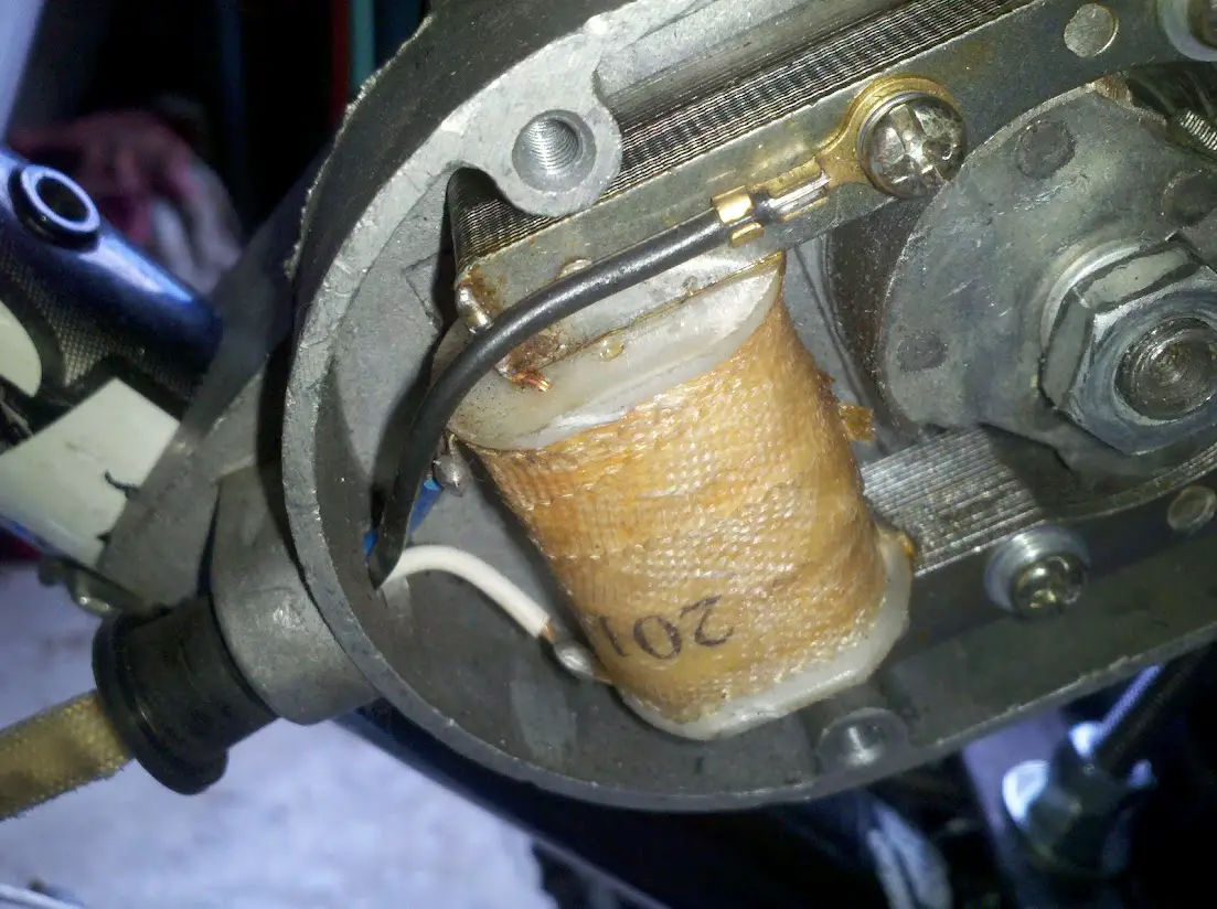
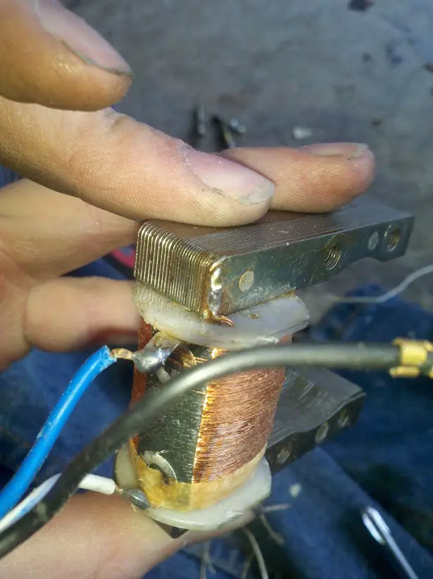
I'm not "opening" anything other than the mag cover on my engine. Let me detail the "re-wiring [of] the frigg'n magneto": Take the ground wire off of the mag (which currently is bolted to the mag via a crimp on hoop tongue terminal, the way the chinese made it) and solder it directly to the engine. Next, I will strip the insulation from a small section of the wire to solder it to the common ground, where the blue and white wire are currently soldered to the magneto core (Note: I will also attempt to pull the corner where the wires are soldered away from the main block to ease the task of heating the materials to get the proper wetting). Finally, I will attach the free end of the black wire to the CDI, completing the circuit.
This is schematically the same circuit as it was previously, just with a bonded ground and better overall connectivity.
Furthermore, I am no novice. I make no claims to be an expert, but I am apprenticed to a master.
Multimeter? Yes, I have two. Learn how to use it? I am already there. For instance, did you know you can measure the available amperage of a power source (such as the mag) using the volt scale? It's easy, you just introduce a resistor with a known value, and do a little algebra. Ohm's law, if you didn't know, can be expressed as I=V/R. If you have a 10 ohm resistor, and you read 6 VAC with your meter in series, you have a 0.6 A available source.
I have a few words of advice for you. For your safety, and those whom you give your "lessons" to, you should first test your meter on a known good circuit before testing a wall outlet. If you don't, and your meter is dead, you will be too.
These pictures illustrate what I mean by the layers of the magneto core (the "chunk of metal" I was referring to in a previous post), and the fact that the black wire is not soldered to the mag.
I'm not "opening" anything other than the mag cover on my engine. Let me detail the "re-wiring [of] the frigg'n magneto": Take the ground wire off of the mag (which currently is bolted to the mag via a crimp on hoop tongue terminal, the way the chinese made it) and solder it directly to the engine. Next, I will strip the insulation from a small section of the wire to solder it to the common ground, where the blue and white wire are currently soldered to the magneto core (Note: I will also attempt to pull the corner where the wires are soldered away from the main block to ease the task of heating the materials to get the proper wetting). Finally, I will attach the free end of the black wire to the CDI, completing the circuit.
This is schematically the same circuit as it was previously, just with a bonded ground and better overall connectivity.
Furthermore, I am no novice. I make no claims to be an expert, but I am apprenticed to a master.
Multimeter? Yes, I have two. Learn how to use it? I am already there. For instance, did you know you can measure the available amperage of a power source (such as the mag) using the volt scale? It's easy, you just introduce a resistor with a known value, and do a little algebra. Ohm's law, if you didn't know, can be expressed as I=V/R. If you have a 10 ohm resistor, and you read 6 VAC with your meter in series, you have a 0.6 A available source.
I have a few words of advice for you. For your safety, and those whom you give your "lessons" to, you should first test your meter on a known good circuit before testing a wall outlet. If you don't, and your meter is dead, you will be too.
Cool, everyone should have a multimeter, I got my first one 30 years ago in electronics school and had at least one ever since.
I even had a Techtronics dual line Oscilloscope for years which would be REALLY handy to see what the mag does compared to the spark plug out, but it was old and when it died I pitched it.
The Magneto ground I refer to is circled in your pic.

See the two copper wires coming up and soldered to the mag housing?
Those are the two opposite ends of the two winding wires, blue and white.
Yours looks good to me, but to verify Ohm the blue wire to the motor body, you should get 300-350 Ohms in resistance and not an open.
If the mag grounds to the motor, and the motor grounds to the bike (Ohm it to check), you can hook your CDI black wire on any metal piece like a water bottle mount hole, the same for the kill button.
Also the schematic does show the ground connections, they just use the universal symbol of 3 lines making an upside down triangle for it.
That infers all of those 'triangle' points are connected, they just don't draw the wire lines for them.
I hope that helps.
I even had a Techtronics dual line Oscilloscope for years which would be REALLY handy to see what the mag does compared to the spark plug out, but it was old and when it died I pitched it.
The Magneto ground I refer to is circled in your pic.
See the two copper wires coming up and soldered to the mag housing?
Those are the two opposite ends of the two winding wires, blue and white.
Yours looks good to me, but to verify Ohm the blue wire to the motor body, you should get 300-350 Ohms in resistance and not an open.
If the mag grounds to the motor, and the motor grounds to the bike (Ohm it to check), you can hook your CDI black wire on any metal piece like a water bottle mount hole, the same for the kill button.
Also the schematic does show the ground connections, they just use the universal symbol of 3 lines making an upside down triangle for it.
That infers all of those 'triangle' points are connected, they just don't draw the wire lines for them.
I hope that helps.
Last edited: