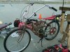
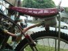
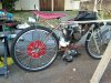
Re: Motor Bike DIY'er build to add side car maybe?
CB thanks for that info, but I need clarification on what you said.
Does this mean that and extended tube to route the air going into the carb was 10” and helped allow cooler air into the carb that was drawn away from the engine. This worked?
Or was this what you felt would help, but then the even short length of the tube had a negative effect so that it was dispensed with? You just had left it like it was?
Which is the true correct one?
==================================================
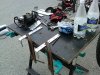
New info and also Idle Not A Problem just to let you know.
Wanted to let you know, I have a good enough idle on this engine without any adjustments using this carb, but at full throttle it starts to miss. I was able to adjust the breaker point gap and gets it a little better than how I had adjusted it once before. I will record how I have it set and zone in on what is best for an overall range of speeds from idle to full throttle.
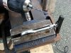
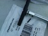
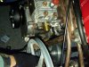
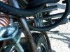
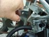
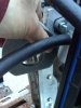
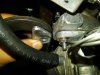
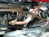
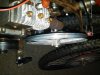
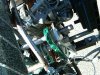
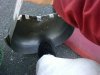
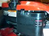
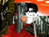
Today though I had checked again to find more information data gathering without changing the gap and found that when I removed a portion of a part attached to my airfilter housing, that I had better medium throttle.
This is a portion that is to later to be attached to a corrugated house to get air up and away from dusty ground but not yet attached. When I saw this I cut away some material that was restricting air flow and put this portion of a cover back on. It was still not as good as it removed fully. Please note the foam airfilter was still in place. It is an old foam filter, but is clean.
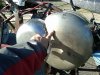
Now here is something I don’t ever suggest anyone ever do, but just for a short while I removed the foam airfilter and ran it (no filter), careful to see that there was no dust present. I am not riding it at this point yet and it was stationary, just the bike with the engine mounted on it and not moving. So what did it do, ran just fine. The range from idle to max perfect, maybe a few every 15 seconds a slight miss. Maybe the breaker points need a little better adjustment.
I know I have to have a filter, but thought maybe a new foam airfilter or even a paper airfilter that may have less air flow restriction is what I intend now.
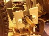
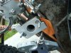
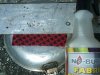
I bought a paper Briggs filter that goes on a Toro Mower and looks to have a similar carb as mine without any needle valve adjustment screw. It will take a little work to get it to go into my airfilter holder that was previously meant for a foam one. I modified it before to get it to work with the new carb I mentioned I have, so no problem and can further make some modification to get it to work with the paper airfilter.
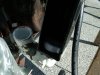
I also noted that the same arrangement of gravity feed gas tank and bowl float carb on the Toro Mower as my engine except that I have an additional 3” higher the out flow from the bottom of the gas tank.
What I wonder is, does this really affect the richness or only the possibility that the float valve may not seal gas from leaking through into the bowl and then as a result change the richness. It does not leak when stopped so I was thinking 3” does not matter.
Ideally the float height would allow a certain amount of fuel in the bowl that is set precisely to get a metered amount for all range of speeds. If the float is not having a problem leaking at the valve it controls, then I think the float level is a separate issue.
The float then I think should not be messed with unless it is an adjustable float and for good reason to adjust it. The carb I bought a year ago but only just been put into use. So effectively it is new and I am thinking don’t change float level even if it can be adjusted which most the cheap ones cannot be.
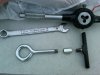
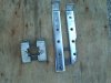
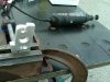
With the elbow bend and a few other straight through adapters only changing the mounting, I think it will eventually be solved by a less restrictive airfilter and also maybe some breaker point adjustment.
I will though go and take my adapters off and trim the gasket material so that the amount of fuel air mixture is not impeded by a slightly smaller gasket inner diameter getting in the way, just to be sure.
It this all goes well I will try also connecting the corrugated hose I intended at first to attach to the airfilter inlet and get air up higher away from dusty ground.
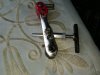
The main thing I have to remember is that the Vacujet Carb and gas tank I tested out the engine before ran perfect, and it has an adjustment mixture screw, but not an idle adjustment screw. At least one is better than nothing I know, as this cheap carb without any adjustment as far as I know as there are no needle valves to tweak, seems to be making this a bit difficult. I have a video on Vimeo uploaded of the beast running great, so I hope to be able to have the newer carb have the same results with the engine.
I do believe I will put the vacujet carb with its oil bath airfilter just to see if the breaker points are set well enough to adjust the carb and get engine running well at all speeds. If there not I set them to get it right, and be back at square one as so to speak.
Then I feel that just changing the carb to the newer bowl float type I should not have to adjust the breaker points anymore, just get the airflow OK so it is not too rich a mixture. It is a way of isolating what is known good and going from there so to not get too complicated.
Probably said enough now, so I’ll stop and see what happens next.
MT
Saw this video on Youtube about float level adjust for racing performance Briggs Engine Carb
http://www.youtube.com/watch?v=VnyrRtaA2Wo
Here is a link pdf on Briggs Engine and there is information on Carb Bowl Floats, problems and adjustments
http://www.briggsandstratton.com/su...n_troubleshooting_detail_reference_guide.ashx


")