Weed Eater Friction Drive Bicycle

GoldenMotor.com

landuse

New Member
Nov 21, 2011
64
0
0
Pietermaritzburg, South Africa
I have posted this build on other forums as well, but I thought that I would probably get more help and advice if I reach more people.

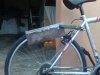
I have been having some withdrawal symptoms since I finished my minibike, so I have now decided what my new project is going to be. A friction driven weed eater bicycle!! I have already gotten started with the whole project.

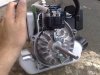
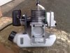
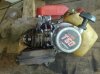
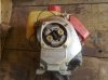
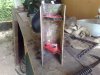
I have decided to use an old Mitsubishi T50 engine that I got off a trimmer. As far as I can tell, it is a 26cc engine. I just hope it has enough guts for what I am going to use it for. I also decided to be a little more elaborate than your average back yard friction drive that you see on the net and on YouTube. I have decided to try and duplicate the Staton/DAX friction drive setup.

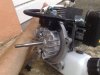
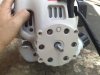
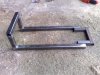
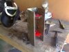
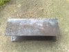
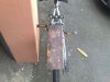
So far, I have cut the steel plate into 3 equal sections and welded them together to make the U shaped housing that everything is going to bolt to. I then measured the bolt pattern of the clutch housing for the motor, and drilled the holes for that. Due to the rotation of the engine, it is going to be mounted on the right hand side of the bike. (I hope I got that right).Trying to get it all not to warp too much was difficult.

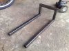
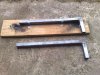
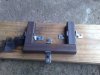
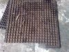
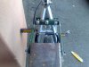
I then cut lengths of steel strips and welded them together for the U bracket that bolts onto the bike frame. As a protection for the bike, I cut strips of rubber off an old car mat and drilled holes in that to fit my bracket.

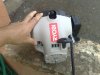
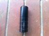
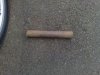
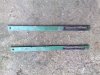
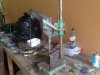
I am going to have to use a contact I have at a machine shop to drill out the holes in the housing for me to fit the bearings into. He is also going to machine the steel bar I have into the roller that will attach to the clutch drum. He only opens shop again tomorrow, so I will get hold of him within a few days.

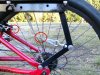
Well, that is where I am at the moment. I have included a few pics of everything mocked up together.
 

Attachments

landuse

New Member
Nov 21, 2011
64
0
0
Pietermaritzburg, South Africa
I got a little more done this weekend. I cut the 2 lengths ofmetal strips that will be attached to the U channel and to the sprocket area to tension the roller against the tyre. (I am not sure what they are called). I had to cut slots at the top of each so that I can tension the channel easily. I had to do this with a grinder again, so it doesn't look too pretty.....but it will work. When I went to the scrap metal yard a week or so ago, I also came across a mechanical drill press that you put your hand drill in. I didn't have a drill press cos they are too expensive, so I got this one for practically nothing. It works great!
 

Attachments

rustycase

Gutter Rider
May 26, 2011
2,746
5
0
Left coast
Gosh, looks like you are doing a fine job!

You'll be a little short on power, but it will be good for the flats, when it's dry.

and Welcome Aboard!

Best
rc

for FD, most motors mount on the left...
 
Last edited:

landuse

New Member
Nov 21, 2011
64
0
0
Pietermaritzburg, South Africa
Thanks rustycase. When I checked to see the rotation direction of the engine, by pulling the recoil, the engine spun clockwise when looking at the clutch shoes. To me this means that I would have to mount it on the right side for it to move the bike forward.

Am I correct, or am I confusing myself?
 

wayne z

Active Member
Dec 5, 2010
1,743
5
38
louisiana
I think the mount them on the left when driving from a roller arrached to the flywheel side of the motor. How arew you going to attach your roller? Are you going to incorperate the clutch similar to a Stanton drive?
 

landuse

New Member
Nov 21, 2011
64
0
0
Pietermaritzburg, South Africa
I think the mount them on the left when driving from a roller arrached to the flywheel side of the motor. How arew you going to attach your roller? Are you going to incorperate the clutch similar to a Stanton drive?
Yup. If you have a look at the second pic of my engine, you will see the clutch shoes that will be mounted inside the clutch drum and roller assembly in the U channel bracket
 
Last edited:

rustycase

Gutter Rider
May 26, 2011
2,746
5
0
Left coast
You're right Land, nothing wrong with ur thinkin!

Drive roller must rotate opposite direction of travel intended.

and gosh... WayneZ is an expert! Do what He says! :)

Best
rc
 

landuse

New Member
Nov 21, 2011
64
0
0
Pietermaritzburg, South Africa
Yesterday I handed over my U channel to a machinist to drill the holes for the bearings and machine a roller for me. Because I am small fry business for him, I might have to wait a little bit before he gets the time to do my work. I will keep you all updated though on the progress.
 

landuse

New Member
Nov 21, 2011
64
0
0
Pietermaritzburg, South Africa
Well.....I was given a brand new Ryobi 30cc engine last week. I have decided to make another friction drive out of this one, and maybe hold off on completing the one that I started this thread with.

I have already done some work to get this one off the ground. I will be drag starting the engine, as I couldn't find a way of putting my bike peg on the shaft without removing the pull start. I have decided to make a simple bracket, that will pivot on a U shaped bracket attached to the frame. I will weld 2 strips of metal to the frame so that I can bolt the engine on.

I am going to be using turnbuckles and springs to tension the motor onto the wheel. I still have to weld up the U bracket for the frame, and buy the correct springs. I am going to have a look at springs today. It might take me a few tries to get the correct ones.

Here are some pics of the setup I have so far.
 

Attachments

cannonball2

Well-Known Member
Oct 28, 2010
3,682
221
63
Colonial Coast USA.
The Ryobi you have is actually a Homelite derived engine. Should work fine. You are really building a sturdy mount for it! It should allow you at install just about any small engine in the future. That would easily support an HF Preadator, 97cc Lifan, small Briggs etc..
 

landuse

New Member
Nov 21, 2011
64
0
0
Pietermaritzburg, South Africa
The Ryobi you have is actually a Homelite derived engine. Should work fine. You are really building a sturdy mount for it! It should allow you at install just about any small engine in the future. That would easily support an HF Preadator, 97cc Lifan, small Briggs etc..
LOL. I know what you mean about the sturdiness. It was the only steel that I had laying around, so I just used it. At least I know it won't break. :D

I am also going to make a handle/bar that will come up close to the centre tube of the frame so that I can engage and disengage the engine when I need to using a pivot action.
 

cannonball2

Well-Known Member
Oct 28, 2010
3,682
221
63
Colonial Coast USA.
I built one bike with an engagement lever and though it worked well I was rather awkward, especially if used with hand brakes. The scissor lift with a clutch handle on the handle bar is much easier, just like riding an M/C, especially if in traffic.
 

landuse

New Member
Nov 21, 2011
64
0
0
Pietermaritzburg, South Africa
I built one bike with an engagement lever and though it worked well I was rather awkward, especially if used with hand brakes. The scissor lift with a clutch handle on the handle bar is much easier, just like riding an M/C, especially if in traffic.
How would the scissor lift work? I cant visualize it. Have you maybe got a pic that I can look at
 

cannonball2

Well-Known Member
Oct 28, 2010
3,682
221
63
Colonial Coast USA.
Probably an inch plus, just depends on the geomometry. There is less effort the closer to vertical it begins, but more travel the lower it begins, but too hard to pull generally. On a FD as long as it clears the tire its disengaged. Another advantage is you can easily vary the down force on the fly with the adjuster on the clutch handle. Ones with the bigger adjusting wheel are best but the usual ones work also. I am lifting a 22lb engine with pretty heavy spring down loading with no problem.
 

landuse

New Member
Nov 21, 2011
64
0
0
Pietermaritzburg, South Africa
What do you mean by adjusting wheel? Do you mean in the clutch handle? What cable did you use? Was it a normal bicycle cable. Did you connect two cables together with some sort of copper tubing? I have included one of your pics with circles round the parts I am speaking about.

Sorry for all the questions, but I am not the most mechanical person.

Another question....Did your cable fit perfectly in the M/C handle, or did you have to do some customisation with the end of the cable?
 

Attachments

Last edited:

cannonball2

Well-Known Member
Oct 28, 2010
3,682
221
63
Colonial Coast USA.
A universal M/C or ATV cable works fine. A bike cable should work on the engine you have, probably with a longer bicycle brake handle. My heavier engines use a 1/16" cable.This was a recycled ATV brake cable. I had to lengthen it to make the clutch cable. That is a nicropress fitting, sometimes called a cable ferule. They are squeezed together with a special tool. It is simply lengthening the cable. The one at the end is terminating the cable around a cable thimble, it spreads the cable around a desirable radius and provides wear protection. This is the proper way to make cables, I do it this way because I made aircraft cables in the past and have the tools. Now after that lesson, you can also use the ferule and solder the cables in place if you have no way to squeeze one, and you can squeeze em in a vice or big pliers, but it aint ideal.

The adjusting wheel I speak of is at the handle and is the common cable adjuster found on an M/C. If I dont need a lot of download, say on the flats, I shorten the cable to keep the engine load off the tire, less wear. If I come to a steep hill I just lengthen the cable a few turns to load the tire more to climb the hill. This is useful with the bigger bore high torque engines.