Weed-whacker DIY build

GoldenMotor.com

CaptainObvious

New Member
Oct 19, 2014
12
0
0
Moncton, NB
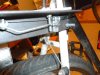
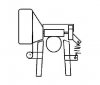
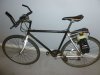
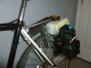
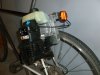
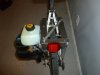
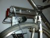
I was surfing youtube a little while ago and stumbled across videos of people who had mounted weed-whacker and chain-saw motors on their bikes. Found a Ryobi 31cc motor on kijijji for $25.00 and got the bug.

Here are a handful of photos and a link (https://plus.google.com/102989797968868176497/posts/WxUZx7tdVwA) to a short writeup on the build and initial testing.

I still have to mount a kill switch on the handlebars and fiddle with the gas mix to find out what it likes, but otherwise this beast is in shakedown mode. I may have to invest in a radar detector because this thing goes.

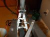
As noted in the writeup, the friction drive with a BMX peg does not work well when the road is wet. An innertube segment stretched over the peg and epoxied lasts about 20 minutes before it is shredded. Any suggestions as to how to improve traction are appreciated. I am considering drilling 1/8 or smaller divots (not all the way through) around the contact band of the peg, but I'm not yet sure how that would work or whether it would abrade the tire unduly without improving traction much.
 

Attachments

wheelbender6

Well-Known Member
Sep 4, 2008
4,059
221
63
TX
Clean install, CO. I love the DIY installs because none are exactly alike. Looks like you mounted the engine with the cylinder pointed down, for a low center of gravity.
Some people have gotten better traction by etching linear grooves into their roller, parallel with the rear wheel axle. Probably easier than drilling holes in the roller.
Tinkering with the tension of the roller against the rear tire will also help.
 

Ludwig II

Well-Known Member
Jul 17, 2012
5,071
783
113
UK
There have been comments that the right grade of polyurethane roller improves wet grip. Several old European friction drivers used a much bigger roller, with a reduction drive from the motor. I'm curious to see whether having a separate idler roller on the back of the tyre, pressing on it in wet weather, would clear any worthwhile quantity of water off it, I don't think anybody's tried it.
 

CaptainObvious

New Member
Oct 19, 2014
12
0
0
Moncton, NB
There have been comments that the right grade of polyurethane roller improves wet grip. Several old European friction drivers used a much bigger roller, with a reduction drive from the motor. I'm curious to see whether having a separate idler roller on the back of the tyre, pressing on it in wet weather, would clear any worthwhile quantity of water off it, I don't think anybody's tried it.
It is unlikely that would work. If the tire is damp the steel peg slips very easily. I roughed up the peg for gluing with a round file. Subsequent to losing the innertube, fifteen kilometres of driving smoothed the file markings. I anticipate that within a few tens of kilometres, the peg will be mirror-smooth. I was using five-minute epoxy, which may not be ideal. Epoxy geared towards auto-body work might be better, but the innertube rubber simply isn't going to cut it. One might try a piece of bicycle tire, but regardless of adhesive at high-rpms it is going to come loose. all in all it is a fairly tough problem. A larger roller would help but that is not practical with this design. Belt drive is probably the best option to avoid the problems with friction drive, but in the short term I am stuck with FD.
 

CaptainObvious

New Member
Oct 19, 2014
12
0
0
Moncton, NB
Clean install, CO. I love the DIY installs because none are exactly alike. Looks like you mounted the engine with the cylinder pointed down, for a low center of gravity.
Some people have gotten better traction by etching linear grooves into their roller, parallel with the rear wheel axle. Probably easier than drilling holes in the roller.
Tinkering with the tension of the roller against the rear tire will also help.
The orientation of the motor is the same as in its original role as a trimmer. The gas tank is held in place by plastic tabs on the back plate and flywheel shroud, as supplied. Tension is good, but the issue is contact area which is limited by the roller diameter.

Two or three rings of M3 set-screws rounded and peeking just above the surface of the roller would probably work, but drilling and tapping for them would be a major bit of work. My drill press is in storage, so I wouldn't even attempt such a thing. You'd need 20+ set screws to make it feasible. Another possibility is to use a stick welder to dab bumps on the peg. Don't have one of those either ATM.
 

CaptainObvious

New Member
Oct 19, 2014
12
0
0
Moncton, NB
small engine + big roller plus unsupported roller on overhung crankshaft weediemotor = short life..
That is a good point, but the question is: "how short"?

The Ryobi has what seems to be one crankshaft bearing. On the plus side, it ought looks like a roller-bearing (as opposed to ball-bearing) and is about 1" long. Without a full teardown it is impossible to assess its quality. Nevertheless, the force on it is relative to the tensioner, which I estimate is somewhere near 50 lbs. Not so much really. Consider motorcycles with a swing arm that attaches to only one side of the wheel, or airplane landing gear similarly attached. I suggest that the problem as you state it is overblown, but how much so is anyone's guess.

As with so many things the only thing to do is to run it and see how long it actually goes.

I don't plan to tempt fate too much; which means moderate speeds, releasing the tension when it is parked, etc. Oh, and I'm using 30:1 instead of 40:1 so as to err on the conservative side. One problem is downhill grades which I'm told tend to starve 2-stroke motors of lubrication. So I'll probably want to brake when going down hills to limit speed.
 

Slogger

Member
Sep 8, 2014
544
4
18
nohio
I forget the size, but in the 90's I converted a Ryobi weedwhip engine (the $89 one) for model airplane use. Someone sold me a mount and pipe for it, the cooling fins on the flywheel were milled off, and I tested it with a top-flite 18X6 wooden prop.
After a little running time, I tached it at 7,600 RPM, which is somewhere between 2 and 3 horsepower. It was going to power a 9 foot span Piper Cub. I never did build one, and the engine is stored. It ran great when I put it away.
It has a Walbro carb. About 11mm, maybe.

I wonder if that carb could work on a china girl. ?
 

CaptainObvious

New Member
Oct 19, 2014
12
0
0
Moncton, NB

CaptainObvious

New Member
Oct 19, 2014
12
0
0
Moncton, NB
A minor update:

One of the M5 bolts attaching the mount to the bike frame sheared off yesterday. On the right side, the profile was mount, washer, nut, 1mm gap, nut, washer, angle iron, 35mm bolt head. It sheared at the gap. A close examination showed visible signs that it was flexed over 15km or so before breaking. Lesson learned? The mounting points must be tight to absorb stress from angle-iron flex. Obviously a concern is shearing at the frame which would leave half the bolt lodged in the welded 'nut' and therefore problematic to extract at the side of the road. Solution? 5mm threaded rod cut in 6cm lengths. This allows some of the rod to protrude on the inside of the mount which makes extraction super easy if one should shear off again. The attached photo shows the new mounting arrangement. I think the threaded rod is made from better steel, so it's win-win.
 

Attachments

CaptainObvious

New Member
Oct 19, 2014
12
0
0
Moncton, NB
I forget the size, but in the 90's I converted a Ryobi weedwhip engine (the $89 one) for model airplane use. Someone sold me a mount and pipe for it, the cooling fins on the flywheel were milled off, and I tested it with a top-flite 18X6 wooden prop.
After a little running time, I tached it at 7,600 RPM, which is somewhere between 2 and 3 horsepower. It was going to power a 9 foot span Piper Cub. I never did build one, and the engine is stored. It ran great when I put it away.
It has a Walbro carb. About 11mm, maybe.
How do you get HP from RPM? During my research it turned out that these Ryobi 31cc motors are very popular among the model airplane crowd. The 11mm venturi in your carb is preferred in comparison to the 8mm venturi common to the motor I have. Tuning the motor is going to prove problematic since there is no low-speed adjustment and this high-speed needle adjust is protected by a funky head which requires a special tool from Walbro. Low and mid-range power is not so hot so far (but I'm not yet running 87 octane fuel) but once it gets above 4k RPM it climbs hills like a champ. It 'feels' like it has more than two or three HP but it is difficult to judge these things accurately without instrumentation.
 

Slogger

Member
Sep 8, 2014
544
4
18
nohio
How do you get HP from RPM? During my research it turned out that these Ryobi 31cc motors are very popular among the model airplane crowd. The 11mm venturi in your carb is preferred in comparison to the 8mm venturi common to the motor I have. Tuning the motor is going to prove problematic since there is no low-speed adjustment and this high-speed needle adjust is protected by a funky head which requires a special tool from Walbro. Low and mid-range power is not so hot so far (but I'm not yet running 87 octane fuel) but once it gets above 4k RPM it climbs hills like a champ. It 'feels' like it has more than two or three HP but it is difficult to judge these things accurately without instrumentation.
There was a formula used on airplane engines, static rpm of a given prop would be enough to calculate peak hp.
The actual number is lost to mists of bad memory, but I remember it was about 3hp and an angry little guy. I knew it would fly the big Cub about 55 mph.
I about threw my shoulder out flipping the prop to start it, until I wised up and got a heavy duty starter that could spin it up.
I do remember it reached 7600 on the nose. Too bad I wiped out its air cooling fins, or it could be used for something else.edit: Mine popped away at idle and accelerated cleanly, although I never flew it. Mid range seemed fine. It actually ran great after it was started, on a mix of 32/1.
 
Last edited:

cannonball2

Well-Known Member
Oct 28, 2010
3,682
221
63
Colonial Coast USA.
I have converted many Ryobis over the years for R/C usage. They are a nice running conversion when properly done. They are not big HP makers. I think in the stock form they are no more than 1hp. In the R/C setting they are best suited to big, lightly wing loaded floaters. The 11mm two needle carb is a good replacement. Much bigger and throttle response suffers. The ideal prop was an 18/6 with rpms somewhere in the low to mid 7k static. The reason I am stating these specs if you search over at R C Universe there are calculators that will determine HP. I doubt in reality HP exceeds 2 if that much. The purpose built DA 50 was only around five and it had an advancing ignition and much more aggressive timing.
There were several versions of the Ryobi for various applications. They had different positions of the rods pin. There was one that was superior, if memory serves the pin was noticeably advanced.
A search at RCU will reveal much, there were many threads on modding, re- timing and tuning. This site probably has more info on the Ryobi than any place
I converted one of these to Glow fuel, was a great runner and produced about twice the power. Drank fuel though, and required an electric starter or it was just as happy to run backwards if hand started.
 

Ludwig II

Well-Known Member
Jul 17, 2012
5,071
783
113
UK
I have a 31cc Ryobi lying about, it might get used for Mk2 bike, if I can't get the size of antique motor I want. It has a long drive shaft and the overhung crank (in this, it resembles many of my friends). I think, and prove me wrong if I am, that the crankshaft actually uses side by side ball bearings.

I looked at the problem of exerting pressure in a direction it wasn't designed for, and came up with the idea of a pillow block bearing at the free end, the bearing being attached by a long bracket to the motor.

Now I get clever. Pivot the motor so the shaft moves up and down across the back wheel, and only tension the free end and the bearing. This is a picture which tries to explain it, but it might not.
 

Attachments

Ludwig II

Well-Known Member
Jul 17, 2012
5,071
783
113
UK
Rather conveniently, it can also shroud the roller so idiots can't do idiot things like ask if the roller is grippy and sticking a finger in to find out.
 

CaptainObvious

New Member
Oct 19, 2014
12
0
0
Moncton, NB
I do remember it reached 7600 on the nose. Too bad I wiped out its air cooling fins, or it could be used for something else.edit: Mine popped away at idle and accelerated cleanly, although I never flew it. Mid range seemed fine. It actually ran great after it was started, on a mix of 32/1.
I was running it on Coleman camp fuel earlier today but the mid-range sucked, and lacking the special tool I could not adjust the carb. Running 87 octane at 30:1 resulted in much improved acceleration and it wouldn't bog down in the mid-range. It's probably a good thing that I'm running it with the head down as that ought to improve the lubrication of the cylinder and ring(s) and extend its life. I advanced the timing three or four degrees which gives it a satisfying sound at low RPM and improves torque in that range.
 

cannonball2

Well-Known Member
Oct 28, 2010
3,682
221
63
Colonial Coast USA.
Yep its a double bearing crank all on one end. Don't worry about stressing the bearings. In the R/C applications the bearings survived thrust loadings they were never designed for. The loadings imposed by a vertical application such as an FD are handled easily across the two bearings. This is true of the original engines. There have been several versions and I suspect bearing quality has diminished over the years.
I bought my Dad a new Ryan for Fathers day many years ago, I believe it was an original design by OMC. A very simple yet well designed unit, direct drive with no clutch, hence the long crankshaft.
 

CaptainObvious

New Member
Oct 19, 2014
12
0
0
Moncton, NB
I have a 31cc Ryobi lying about, it might get used for Mk2 bike, if I can't get the size of antique motor I want. It has a long drive shaft and the overhung crank (in this, it resembles many of my friends). I think, and prove me wrong if I am, that the crankshaft actually uses side by side ball bearings.
I can't say with authority one way or the other. Just from the way it looks I would guess a roller bearing, but there's no telling without an X-ray or full disassembly. If two ball-bearings that's not so bad, but I read somewhere (perhaps RCU) that it had only one bearing.

I looked at the problem of exerting pressure in a direction it wasn't designed for, and came up with the idea of a pillow block bearing at the free end, the bearing being attached by a long bracket to the motor.

Now I get clever. Pivot the motor so the shaft moves up and down across the back wheel, and only tension the free end and the bearing. This is a picture which tries to explain it, but it might not.
The physics is such that you're going to have 50% or so of the force on the crankshaft bearing(s) no matter what you do. Bearings are in general fairly hardy things and I doubt that a 80-100lb moment is going to wreck them all that quickly. Note that if there are two bearings the one on the outside will be rather dry. That's another reason to suspect a roller bearing. But anyhow, a pillow block will take a considerable fraction of the stress and cannot be a bad idea. In my case, financial constraints mean that I won't be able to do anything clever in that regard for some time, and anyhow the shaft is short so I would have to run an external bearing on the inside surface of the peg. Doable perhaps with a little cleverness.

In any event I've put 50+ km on it in the last week and all I need to say is that it Just Works(tm).
 

Citi-sporter

Active Member
Jun 16, 2014
206
43
28
North Bend, Or,
That is a good point, but the question is: "how short"?

The Ryobi has what seems to be one crankshaft bearing. On the plus side, it ought looks like a roller-bearing (as opposed to ball-bearing) and is about 1" long. Without a full teardown it is impossible to assess its quality. Nevertheless, the force on it is relative to the tensioner, which I estimate is somewhere near 50 lbs. Not so much really. Consider motorcycles with a swing arm that attaches to only one side of the wheel, or airplane landing gear similarly attached. I suggest that the problem as you state it is overblown, but how much so is anyone's guess.

As with so many things the only thing to do is to run it and see how long it actually goes.

I don't plan to tempt fate too much; which means moderate speeds, releasing the tension when it is parked, etc. Oh, and I'm using 30:1 instead of 40:1 so as to err on the conservative side. One problem is downhill grades which I'm told tend to starve 2-stroke motors of lubrication. So I'll probably want to brake when going down hills to limit speed.
Back in the 90's a local home DIY guy in our bike shop's neighborhood was building friction drive weedie engines for kid on BMX bikes and other bicycles.

And these were little Homelite and Ryobi overhung crankshaft engine conversions. Most of the kids with these came in for various repairs, parts, and what-not, and with my just casually looking over these, I noticed that on most of these installs the engines had some slop and looseness axially in the crank main bearings. Some way worse than others. Despite what you believe, most ball bearings, if they are in a side loading use, should be well separated. And yes these are ball bearings, a look inside my Ryobi 825r confirms this.

It's not a matter of if, it will happen with this use that they weren't designed for. Most cheap weedeaters drive either a solid or flexible shaft that applies little to no side loading. On an unsuspended rear wheel mount this engine will bounce up and down on the tire with every bump, not to mention the twisting force the drive roller will add.

The other downside of this is that the rod bearings will have accelerated wear from the mis-alignment.

I've seen it, it does happen.