Piston position to set Valve / Tappet Clearance on Valves

GoldenMotor.com

MEASURE TWICE

Well-Known Member
Jul 13, 2010
2,742
1,212
113
CA
So I have heard for my Briggs 70's era model 80204 0430 3hp 4 stroke engine, that the piston position should be 1/4 inch down from top dead center to set the gap (valve / tappet clearance). That was from the lawn mower shop guy.

I saw that said the same on the Briggs site:

http://www.briggsandstratton.com/eu/en/support/faqs/servicing-the-valves

I 1st however had seen this pdf:

http://www.oldengine.org/members/murphy/Briggs & Stratton Repairman's Handbook.pdf

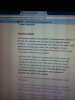
In the pdf I did not see on page the same info. It said as in the jpeg I copied on page 41 where it says to have piston at highest point (think TDC), then rotate flywheel 180 degrees. That is how I did it.

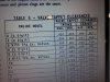
I only changed the intake for adjustment as before it was no gap. I set at 0.007 inch in the range OK for the table 5digit A or B 0.005" to 0.007" intake valve clearance.

Since it runs but won't idle now, I'm thinking totally separate problem. Cleaning or replacing the carb, fuel-line, filter is what I am to do. It was actually intermittent idle, and when it would not idle it cut out. At above throttle it never cut out and kept running.

Just for thought, where it is the setting if that 1/4"difference piston being moved down from TDC, would my measurement for gap be off?

I think since the 1/4"down would have the lobe of the intake cam already pushing sooner on the tappet so the gap would have been less to start with. Effectively I think that means that (strike this out) ---> I could have taken off more of <--- (strike this out)the bottom of the valve stem to get the measurement right for the gap. (I actually took too much according to new method (If And Only If It Applies, IFF to my model engine), where otherwise on website 1/4 inch ATDC (AFTER Top Dead Center)


So, I think if after seeing about fixing the idle issue the way I am intending not messing with the intake valve timing again, only if it does not work, I could just take a little bit more off of the bottom of the valve stem.

In any case, prior to the intake valve being adjusted it was no gap and gas was spraying for 1/3rd of the compression stroke out the throat of the carb at the air-filter and wetting it. After a while it was choking the air flow and wasting air-filter way too prematurely. Now with a intake gap at 0.007", the way I measured as in the pdf, I can even take a whiff of the air-filter and not even smell gas on it after a few minute of test time at high revs.

Any reason of the difference for where the piston should be located with respect to TDC in the different methods greatly appreciated.

Thanks

MT

PS, I think maybe the pdf is telling for 5 digit models but, I was thinking 80202 was 5 digit. Maybe error as it really might be all 80202 0430.

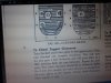
Based on the last pic image of the cover of book in jpeg by Briggs it does say cost being $1 for the manual. I think it is for older engines like my 5S and 6S, but not the 80202 0430 and so the newer method for setting valve clearance probably is from the website. I was unsure as they call 80202 0430 not a current model. They say you have to use archives or maybe it is not on the website, I found the copies from Old Engines website. It is from the 70's is what I a pretty sure of.

I'll see if the new carb only 18 bucks and a new filter and line, along with gas tank cleaning do for the idle problem. I'll also inspect the old carb and have carb cleaner to clean and keep the old carb as a spare.

--------------------- correction--------------- see same as above:

I think since the 1/4"down would have the lobe of the intake cam already pushing sooner on the tappet so the gap would have been less to start with. Effectively I think that means that (strike this out) ---> I could have taken off more of <--- (strike this out)the bottom of the valve stem to get the measurement right for the gap. (I actually took too much according to new method (If And Only If It Applies, IFF to my model engine), where otherwise on website 1/4 inch ATDC (AFTER Top Dead Center)
 

Attachments

Last edited:

FFV8

New Member
Oct 29, 2013
551
16
0
Spring Valley NV
The answer to your question is in the first image you posted.

Open the lifter box, and watch the valve. Rotate the crank, and when the valve reaches full lift - mark the flywheel. Rotate the crankshaft ONE FULL REVOLUTION. This puts that same lifter on the backside of the cam lobe.

Set that valve, then repeat the process for the other valve.

After you set the valves, check the magneto clearance, and the points if your engine still has them.

Check the carburetor to cylinder gasket for leaks if you have idle issues.

.
 

MEASURE TWICE

Well-Known Member
Jul 13, 2010
2,742
1,212
113
CA
Thanks guys.

Just note, since I used the one revolution of crank shaft (180 degree rotation of cam lobe is facing away from tappet bottom in 4 stroke engines make) the old method, then if I comparatively needed the newer 1/4 inch ATDC, I may have ground the valve stem a hare too much.

I also posted on Smokstack and had a reply there also, and that's where ATDC I had taken a better note of.

If I used the 1/4 inch ATDC as it states for more current website of Briggs I may have taken a bit more than necessary. A new valve to get stem length back, or lapp, or cut valve and seat to do the same and I could get it set the newer 1/4 inch ATDC method.

The cost to re-cut valve as I hate to use lapping it messes the valve/seat angle and
cost time and money (no tool to do cutting), I expect it is fine the way it is.

I sort of think the newer models engine may use this 1/4 inch ATDC setting to do the measurement of tappet/valve stem gap.

It gets kind of crazy when documentation does not list my exact model engine 80202 0430 Briggs. In addition the time between working on the engine and subsequently a probably totally different issue is arising due to varnish of gas fumes in tank/tank valve/ fuel filter/ fuel line/ and carb and may relate to idle issue, things are a bit harder to decipher!

Hope to get time to rectify the idling issue, but I am happy to not have wet soaked gasoline air-filter after the intake valve stem grinding.

The original carb used the Briggs Vacu-jet type with oil bath air-filter so I never knew of wet paper air-filter starving the engine for air. It probably was degrading the oil in the bath with gas mist if on the next intake it did not suck the gas mist all out of the filter before storing some more there. I mean why intake valve is open with 1/3 upward travel of compression stroke before intake valve is completely closed, just seems really bad.

If for any reason it should have the intake open on the compression stroke, it would mean for a much shorter time, and the change of carb using a paper air-filter would not be advisable. It is just the carb change I had to do then as I could fit the engine on the frame and also use gravity fuel feed with a larger gas tank. I know I always hear, that it not the carb that came with that engine when buying intake manifold gaskets. Yea Yea Yea!

MT
 
Last edited:

MEASURE TWICE

Well-Known Member
Jul 13, 2010
2,742
1,212
113
CA
Below where I last communicated with other on Smokstack and this is what the lawn mower shop guy had been mentioning.

See the wiki link

==================

http://en.wikipedia.org/wiki/Briggs_&_Stratton

Found wiki on this Easy-Spin Starting under innovations.

"Easy-Spin Starting – This compression release, implemented as an extra hump on the intake lobe of the camshaft, was introduced in 1961 to reduce the effort required to start an engine.[10] In 1982, a new U.S. federal safety regulation required lawnmower blades to stop spinning within three seconds of the operator letting go of the handle. The least costly, most common way of complying with the new regulation was to put a flywheel brake on the mower engine, to stop the engine (and therefore the blade) immediately when the handle was released. Briggs & Stratton engineers found engines with the Easy-Spin camshaft were unacceptably difficult to restart after being braked to a quick stop. The Easy-Spin lobe hump was moved to the exhaust valve, but this reduced engine performance. The intake-side Easy-Spin remained in use on Briggs & Stratton's engines larger than those used on mowers subject to the brake requirement, but was discontinued in 1997 due to tightening emission regulations.[11]
"

I sort of wonder how it was troublesome to pull start after a quick stop of the engine by the safety brake required. Could it be that the engine may have stopped occasionally in the middle of a compression or power stroke and that's why.

Not had time yet to do the check of what it measures doing that method and yet to see about idle issue. I can easily check the measurement again with 1/4 inch ATDC. I am doing this to see about my adjustment of the intake valve though.

If I am doing at some other time the measurement of the exhaust valve would still be the same.

And actually from Briggs it seems it does not matter if it is 1/4 down from top ATDC compression or exhaust as it does not specify. It would mean that either does the same and makes sure both valves are in the lowest position and lobes and easy start bump if there is not in position to push on tappet.

=============

From:

http://www.briggsandstratton.com/eu/en/support/faqs/servicing-the-valves

http://www4.briggsandstratton.com/miscpdfs/RNT/Engine Specifications Chart_ms3992.pdf

"With each valve installed in its proper guides in the cylinder, turn the crankshaft (clockwise as viewed from the flywheel end of the crankshaft) to top dead center. Both valves should be closed. Then, turn the crankshaft past top dead center until the piston is 1/4" down from the top of the cylinder."

=========

Thanks
 
Last edited:

MEASURE TWICE

Well-Known Member
Jul 13, 2010
2,742
1,212
113
CA
This was mentioned from a post on Smokstak by a member to my comment about ATDC for the 1/4 below to position the piston down the cylinder to set valve/tappet gap:

On the power stroke, neither valve will be close to opening when the piston is 1/4" down ATDC.
===========================================================================


This would be then if either doing exhaust or intake gap measurement, I would go by that tip and use the compression stroke, and not the exhaust stroke AFTD for that 1/4 below setting to make gap measurements.

--------------------------------------------------------------------------------------------------

My reply and thought about a compression release that is very primitive and how it may not affect power as much at higher rpm of the engine:

With this Easy-Pull Starting extra small lobe on the back side of the cam I had some thoughts on engine power being robbed in comparison to a similar engine without the Easy-Pull Starting extra bump on the back side of the cam lobe:


The other thing I just noticed is:

http://www4.briggsandstratton.com/miscpdfs/RNT/Engine Specifications Chart_ms3992.pdf

The above link from the Briggs Page that mentions the 1/4 down ATDC (compression stroke also shows 80000 engines. This is probably the series that include my 80202 model. The 0430 is the type and further numerals are the serial. Turns out the gap specs still were the same 0.005" exhaust and 0.007" the intake.

I was wondering how bad is it for engine power to have easy-start relating to torque and horsepower. I was contemplating also the difference to the ones only a bit more complex mechanics to use centrifugal weights to stop compression release after the engine starts.

I think the compression release that stop the release after engine starts would fair better.

Just to throw this in as well. I had came across an engine a long time ago that had a pin size hole that started on the side of area next to the exhaust valve under the head. It had a polished indent surface machined and the pin size hole was I see intended and no way a mistake. You know, I took a bright light and found it went to the exhaust port, which by passes the exhaust valve. This is a constant leak as far as I'm concerned. I think that it was for similar starting issue if not the same. It was at the time mid 70's era.

Trying to figure if it would be letting the compression out and affect the power of the engine linearly across the rpm range, I would think not.

I relate it to an unfortunate engine's scored piston and cylinder wall on an engine that still ran. It had way less horse power, but still ran. The thing was to start it you had to pull the recoil a bit faster to get it to start running.

If compression, as I can recall that resisted my arm pulling the starter cord very slowly where it would not start, had not much effort being needed, the faster I pulled so it would start, it resisted more, hence greater compression.

If the permanently drilled pin size hole by passing the exhaust valve at hand pulled recoil start up, and then idle, and then further increased rpm to max rpm is taken into account, the horsepower out put may not be so badly affected at higher rpm.

The leak has not enough time to let the pressure out before top dead center is reached with faster and faster engine rpm?
 
Last edited:

MEASURE TWICE

Well-Known Member
Jul 13, 2010
2,742
1,212
113
CA
I have ran the engine with the carb that was on it before adjusting the intake valve stem / tappet clearance. Note, not the original Briggs Vacu-jet carb with oil bath air-filter that the 80202 0430 Briggs engine originally was sold with. Before although there was no clearance what so ever it ran and idled good enough to use and have the centrifugal clutch so I could idle and the motor bike I made would not move even with brake off on level ground. The wetting of the paper air-filter with the newer type carb was subsequently stopped after the adjustment. Please note I messed up setting the valve clearance since I was missing the notation of Easy-Spin that Briggs does on this engine. That means that the 1/4 down After Top Dead Center is the piston location when using feeler gauge to check clearance. I did not do this so I probably took too much off to get the approximate 0.007 inch I measured when it was at Top Dead Center for the gap setting. So no wetting the air-filter is great. It still needed to idle which it did not. I checked all fuel issues. Rather than rebuild the carb I just bought the same one new for $18. It was just worth it when rebuild kit was a bit more than half that. Guess what still no idle. It seems that it is the intake valve adjustment I need to get with the Easy-Spin specifics to get the gap right and since I did not take that into account it is possibly off too much and does not idle. Since I took then too much off the stem bottom, I just ordered a new old stock OEM Briggs part for $6. I can preserve the angle of the seat and not cut it anymore. It was done by a machine shop for only $5 each valve / seat years ago. I still see the Neway Tools parts for cutting seat angles at over $100 so I don't need another expensive tool is my thought. Just to see what happens before I swap the new intake valve and adjust per Briggs Easy-Spin 1/4 Down After Top Dead Center, I have the Briggs Vacu-Jet Carb I can use with the integrated fuel tank and the Oil Bath Air-filter to see if it idles the engine OK. My bikes construction won't fit with that type of carb since that gas tank won't fit in the frame. That is why I opted for a gravity feed separate fuel tank. If after adjusting the new intake valve proper and if it still won't idle, I may have to get another carb that is gravity feed fuel type with bowl, but it must have adjustments for low idle and high speed. Some people have said that the carb I got will not idle, but it did, although that was when there was no gap for the intake clearance. Hope I don't need another higher cost carb, or else I may just buy a whole new engine or get another used engine.

This is what I have now two of:

Carburetor Replaces Briggs & Stratton 498170, 497586. Includes O-Ring and Air Cleaner Gasket

http://www.amazon.com/gp/product/B006E1EE88/ref=oh_aui_detailpage_o01_s00?ie=UTF8&psc=1