Two Speed Friction Drive

GoldenMotor.com

Egor

New Member
Jan 30, 2008
714
0
0
Hurricane Utah
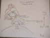
I have an idea for a Two speed friction drive I will post a drawing up and see if anyone wants to build one. If someone wants to they can build one, but please do not start making them for sale, the idea is mine you can use it just for your enjoyment. You can see how it works, the two rollers are running at two different speeds, you pick the one you need by moving the lever. It can be used with a clutch or a direct drive. You could use different size rollers for the speeds but I thought it would work better with larger rollers and determining their speed with the sprockets. The engine could be placed over the center and the drive on the outside, that would make it more compact. It would be fun to take off with a low speed and then shift to high and just cruse along at a quiet pace.
Have fun, Dave
 

Attachments

5-7HEAVEN

Well-Known Member
Aug 2, 2008
2,661
240
63
Egor, I see your idea very clearly. I can visualize the engine mounted on a steel plate and central pivot 1/2" bolt which is perpendicular to the vertical mounting bracket. Under the engine plate are two Staton friction rollers suspended by 5/8" bearings and hangers. The rollers' threaded ends screw onto 2" stubs which mount 10-tooth sprockets. These sprockets align with the centrifugal clutch. The engine's 10T sprocket clutch chains to one friction roller, which then chains to the other spindle. Of course, the bearing's pillow blocks mount via elongated holes which allows chain adjustment. Spacers under the engine adjusts tension to the first friction roller. Springs provide tension onto the tire w/1.25" roller. A strong cable with locking lever controls the shift to the 1.5" friction roller.

I would have considered thid option a few months ago, since I was very interested in shifting for more engine rpm. Instead, I chose the simpler, easier but costlier way by using one engine per wheel, each with different size friction roller.
__________________
Honey, it's just a bicycle. and i REALLY need it to excercise, and to ride it to work.(hehe)
 

deacon

minor bike philosopher
Jan 15, 2008
8,114
9
0
north carolina
I liike the concept but why not a single spindle that has two sizes. One small at the end and longer near the motor, Then lift the motor and move it over to change gears. Seems to me moving the motor would be simpler than building something with more gears and chains. Then again what do I know but I do like the concept.
 

Bikeguy Joe

Godfather of Motorized Bicycles
Jan 8, 2008
11,837
252
63
up north now
Or a tapered roller and as you want more overall ratio, slide the engine over gradually so the roller diameter increases.
 

NEAT TIMES

New Member
May 28, 2008
1,964
1
0
PENSACOLA, FL
A Spring Loaded Chain Or Cogged Belt Idler Would Also Fit. One Over Center Spring, Like The Clutch Set Up On The Golden Eagle Could Control The Drive Tension FOR ROLLER OF CHOICE. A Neutral Detent Mechanism And You Have A Compact Setup. (^)
 

Goat Herder

Gutter Rider
Apr 28, 2008
6,237
20
38
N.M.
This looks very simple I like it cool thinking out of the box!!:eek: I bet it will work great.Keep us posted(^)
 

Egor

New Member
Jan 30, 2008
714
0
0
Hurricane Utah
Deacon I was thinking of the idea that you are suggesting, and I think it would work but the motor would need to move quite a bit. I was thinking along the same line but you would just slide one roller over the other, so on the small one there would be two slots in it, then the larger one would be just moved in and over on the slots, and the engine would sit still. Have fun, Dave
 

Egor

New Member
Jan 30, 2008
714
0
0
Hurricane Utah
Joe, I was thinking of the same line as you, but with a taper you would actually have more than one size of drive on the tire at the same time, so you would have one surface going slower than the other, you could use a very thin tire and that would work. The reason I used the chain, or could be a belt is that you can use a larger rollers and take advantage of the extra surface to drive the tire, IE smaller sprocket on the engine. It is possible to drive one of the rollers directly off the engine and couple the other with a chain or belt.
I don't think it would be necessary to have the bearings move to adjust tension, just put a roller on the slack side of the chain in an elongated slot to take up slack. For the speed selection I was thinking of a spring that would hold neutral (no rollers touching) and then push the lever to a hooked position for each speed, you could even use a tank shifter like the old Indians, just use a leverage joint in the middle. Have fun, Dave
 
Sep 4, 2008
16
0
0
dave i think that your idea or a variation of it would work really well on the vertical shaft motored bikes that i have been building, the taperd roller idea would work if i would work out a way to raise and lower the motor instead of shifting it from side to side. i just finished a 26'' mountain bike with a 6 hp briggs. it runs really well with a 2'' roller,[30 mph]. thats plenty fast enough but my objective was more pulling power which i achieved. if i could use a two speed or a tapered roller set up i wouldn't need as big a motor to get the same job done, which is to pull my 250lb butt down the road. thanks for the brain food!!! vernon
 

Egor

New Member
Jan 30, 2008
714
0
0
Hurricane Utah
Vernon, I was thinking of a way you could drive the wheel, you heard the story about using the rim drive. In my idea I wanted it to be driven on both sides of the wheel, I was thinking of a way to do that, but the rollers need to rotate in opposite directions so you would need gears to do that. But what about having the gears rotate the rollers on both sides and one of the rollers could be larger than the other, or the gears could be different sizes then you would just shift the engine from one side to the other to choose each size and each speed. You could use idler wheels opposite each drive wheel to do the shifting, then you would not stress the rim. What do you think? Have fun, Dave

PS: Ill make a sketch.
 
Last edited:

Egor

New Member
Jan 30, 2008
714
0
0
Hurricane Utah
Heaven, I like the idea you came up with. Putting a drive at both ends also adds redundancy, and if you go off road you have two wheel drive although one is pushing harder than the other, LOL works for me. Have fun, Dave
 

5-7HEAVEN

Well-Known Member
Aug 2, 2008
2,661
240
63
Egor, I can always match the friction rollers if I like. Or when I change to rear chain drive, a 13-tooth sprocket matches the 1.25" spindle.

With twin engines there is much less tire spin in wet weather.

When I ran outa gas on one engine, the other drove me home.

On another occasion, when the front engine conked out, the rear engine drove me home.^5
 
Last edited:

Egor

New Member
Jan 30, 2008
714
0
0
Hurricane Utah
Heaven - Is there a pic of the bike, you have really got me going. I have a bunch of engines I could try one too. Have fun, Dave
 

Egor

New Member
Jan 30, 2008
714
0
0
Hurricane Utah
There were a lot of ideas banging around with this idea, I wonder if any of them we used. I still like the idea that was suggested using a discarded rotary mower engine. There are a million of them around and it would provide all the power ever needed. Have the shaft extend down to the rim with an idler on the opposite side to keep from distorting the rim. Lift the engine slightly to engage the drive to the metal rim with a rubber roller, I wonder if it has been done yet. Have fun, Dave
 

aero07

New Member
Oct 12, 2009
45
0
0
Alabama
I like the two drive roller setup. Has anyone ever tried the two drive roller
concept for increasing the contact area thus reducing wheel slippage.
Looks like it would be a good idea.
 

Egor

New Member
Jan 30, 2008
714
0
0
Hurricane Utah
Camlifter that is the best idea yet. lots of contact area also. I am intrested to hear how it works out. I also like the idea that you don't have to locate the engine out one side. Have fun, Dave