A little bit of fluid mechanics!!!
Velocity profile for a fluid as air in a pipe or intake : ) note "u"is the velocity vector the larger higher the velocity. Fluids have less velocity near the surface due to surface friction or shear. Imagine a lot of people trying to pass inside a hall, the ones nearest the wall will be in contact with it gets stuck to the wall because the friction between them,the ones in the middle will advance more faster. Here is the deal: the air velocity from 0 at molecular level at the wall to the max air speed at the center of the intake. Imagine the velocity vector like a cone inside the intake the top pointing to the direction of the flow. Remember the ideal flow do not exist and the "16v" theory that the air have more speed at the surface and less in the center is totally wrong. The only real situation that occur air velocity increase near the surface is due to acceleration of air cause by the negative pressure generated by an airfoil. Airplanes have negative pressure at the top wing creating lift for the airplane. In cars we use rear wing to accelerate the air at the bottom of wing generating lower pressure down force. But always 0 velocity at the surface.

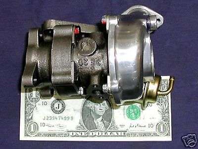
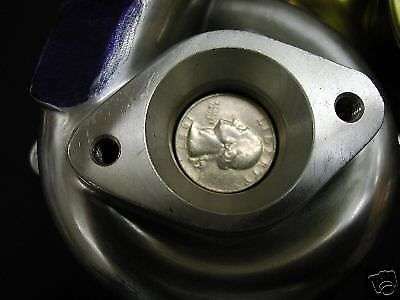
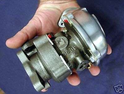
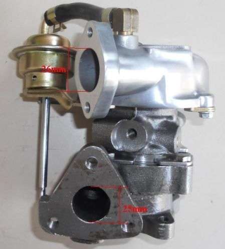
Here we got the three types of flow. The laminar flow is for smooth finish and short intakes including the ones with a normal surface that generate friction, the turbulent flow is for a very long intake or very small diameter intake like the factory one. transitional flow is the middle phase between laminar flow to fully developed turbulent flow. The best intake will be one with a not so smooth finish you can use sand paper 100 grid, the length need to be calculated to create a 25% (just my 2 cents) of turbulent flow to promote a better air and gas mixing without loosing too much air mixture velocity. The intake port must never be polished. For turbo application we can use 220 grid. The bad story is no way to put a turbo on a 66cc or 49cc or 69cc, during the 2008 and 2009 i worked at the sae supermileage car of the university of puerto rico mayagüez campus, we tried to put a smart car turbo( the smallest one available at that moment and i think still today but if i am wrong please tell me) to a 5hp or less B&S engine right now i can remember exactly the hp. The turbo is like a restriction because the turbine prop never move rapid enough to generate boost. END OF STORY NO TURBO HERE UNLESS SOME CUSTOM TURBO IS MANUFACTURED. The internal diameter of the intake must be 19-23mm also the carb this is for stay in the time area parameters you can find more information about this at my post "going case inducted"

For hp
the runnermust be short and have a large diameter. This will provide the air flow needed at high rpm but narowing the power band. Torque is reduced due poor fuel mixing and low air velocity at low rpm. Remember hp means that you could reach a higher speedon your bicycle.
For torque
the runner must be long and have a smaller diameter. this will create a more turbulent flow and due to the friction with the runner surface and high flow the velocity due to a small diameter runner. hp is reduced because at high rpm the air flow became turbulent this will cause the flow velocity decrease
Note: the intake diameter, sand paper grid, intake length. Are just my 2 cents based on personal thinking.
Velocity profile for a fluid as air in a pipe or intake : ) note "u"is the velocity vector the larger higher the velocity. Fluids have less velocity near the surface due to surface friction or shear. Imagine a lot of people trying to pass inside a hall, the ones nearest the wall will be in contact with it gets stuck to the wall because the friction between them,the ones in the middle will advance more faster. Here is the deal: the air velocity from 0 at molecular level at the wall to the max air speed at the center of the intake. Imagine the velocity vector like a cone inside the intake the top pointing to the direction of the flow. Remember the ideal flow do not exist and the "16v" theory that the air have more speed at the surface and less in the center is totally wrong. The only real situation that occur air velocity increase near the surface is due to acceleration of air cause by the negative pressure generated by an airfoil. Airplanes have negative pressure at the top wing creating lift for the airplane. In cars we use rear wing to accelerate the air at the bottom of wing generating lower pressure down force. But always 0 velocity at the surface.
Here we got the three types of flow. The laminar flow is for smooth finish and short intakes including the ones with a normal surface that generate friction, the turbulent flow is for a very long intake or very small diameter intake like the factory one. transitional flow is the middle phase between laminar flow to fully developed turbulent flow. The best intake will be one with a not so smooth finish you can use sand paper 100 grid, the length need to be calculated to create a 25% (just my 2 cents) of turbulent flow to promote a better air and gas mixing without loosing too much air mixture velocity. The intake port must never be polished. For turbo application we can use 220 grid. The bad story is no way to put a turbo on a 66cc or 49cc or 69cc, during the 2008 and 2009 i worked at the sae supermileage car of the university of puerto rico mayagüez campus, we tried to put a smart car turbo( the smallest one available at that moment and i think still today but if i am wrong please tell me) to a 5hp or less B&S engine right now i can remember exactly the hp. The turbo is like a restriction because the turbine prop never move rapid enough to generate boost. END OF STORY NO TURBO HERE UNLESS SOME CUSTOM TURBO IS MANUFACTURED. The internal diameter of the intake must be 19-23mm also the carb this is for stay in the time area parameters you can find more information about this at my post "going case inducted"
For hp
the runnermust be short and have a large diameter. This will provide the air flow needed at high rpm but narowing the power band. Torque is reduced due poor fuel mixing and low air velocity at low rpm. Remember hp means that you could reach a higher speedon your bicycle.
For torque
the runner must be long and have a smaller diameter. this will create a more turbulent flow and due to the friction with the runner surface and high flow the velocity due to a small diameter runner. hp is reduced because at high rpm the air flow became turbulent this will cause the flow velocity decrease
Note: the intake diameter, sand paper grid, intake length. Are just my 2 cents based on personal thinking.
Last edited: